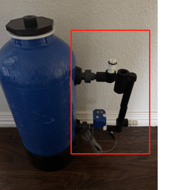
Figure A-1
Overall assembly — blue feeder vessel, lid configuration, and side-mounted manifold and valve arrangement.
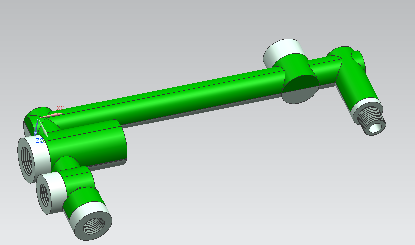
Figure A-2
Manifold assembly — branch geometry, connection points, and side connection orientation.
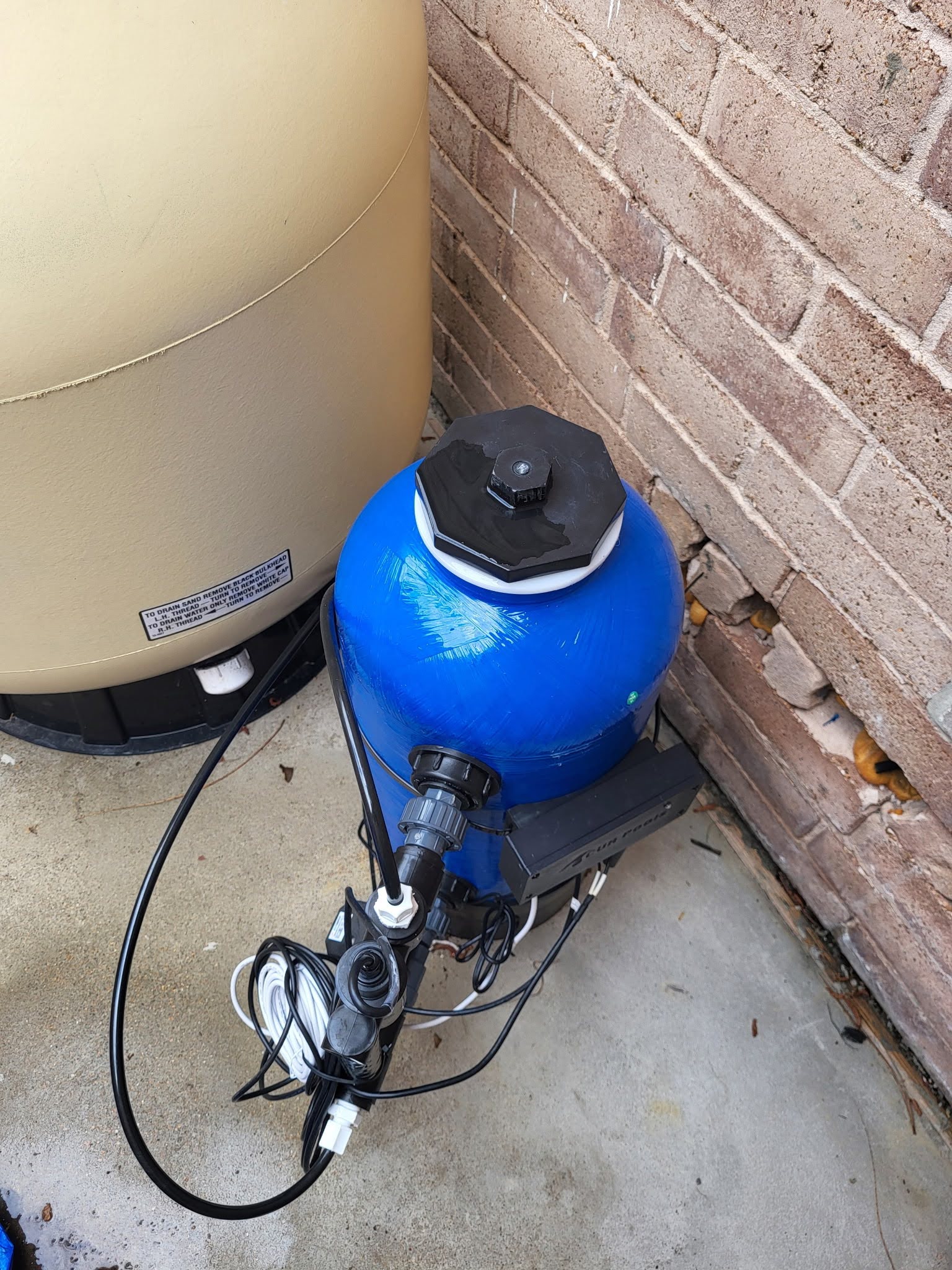
Figure A-3
Installed field view of the CUASCHEM5 assembly connected at the equipment location.
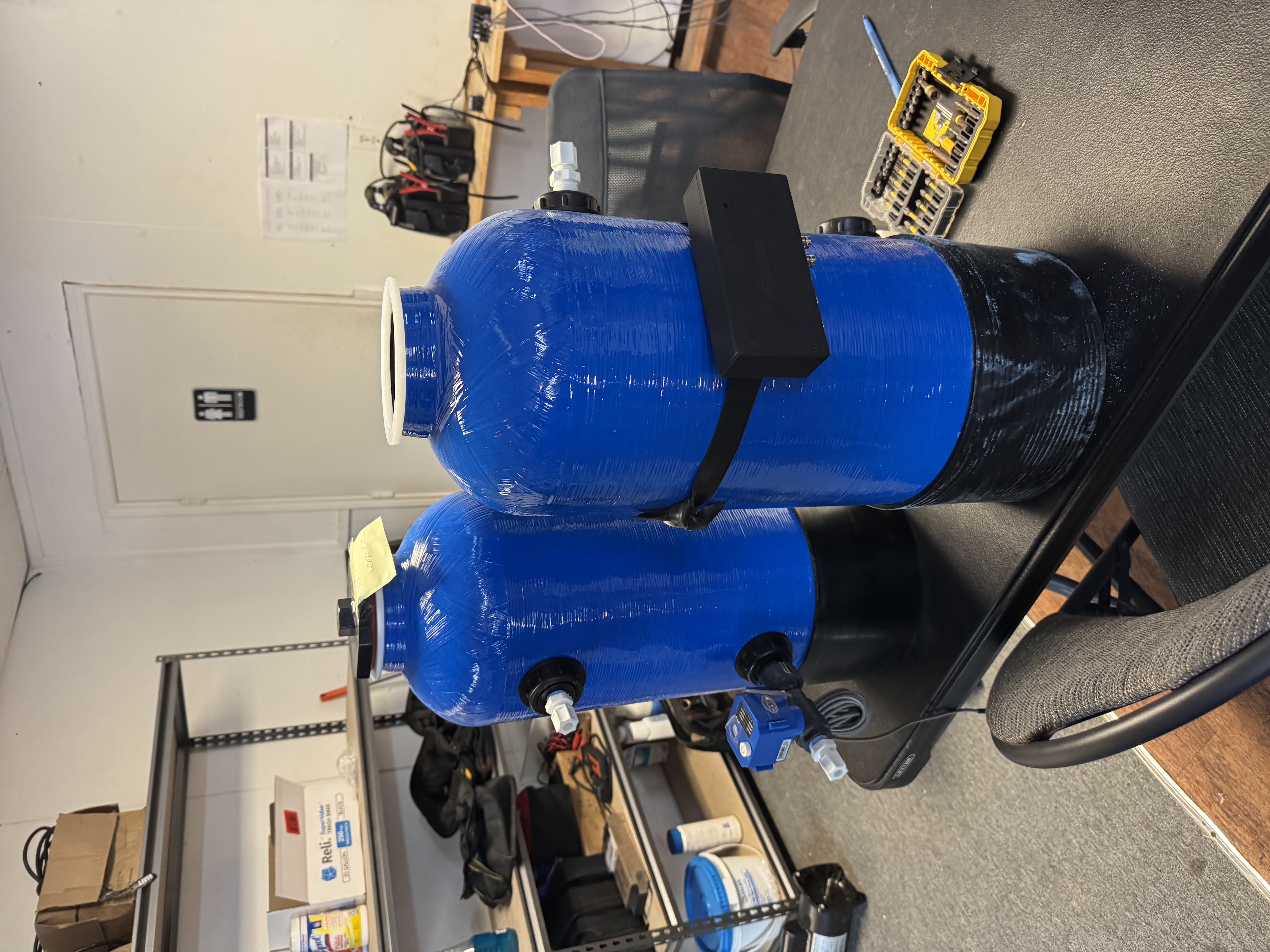
Figure A-4
Equipment-room installation — piping relationship and installed feeder branch hardware.
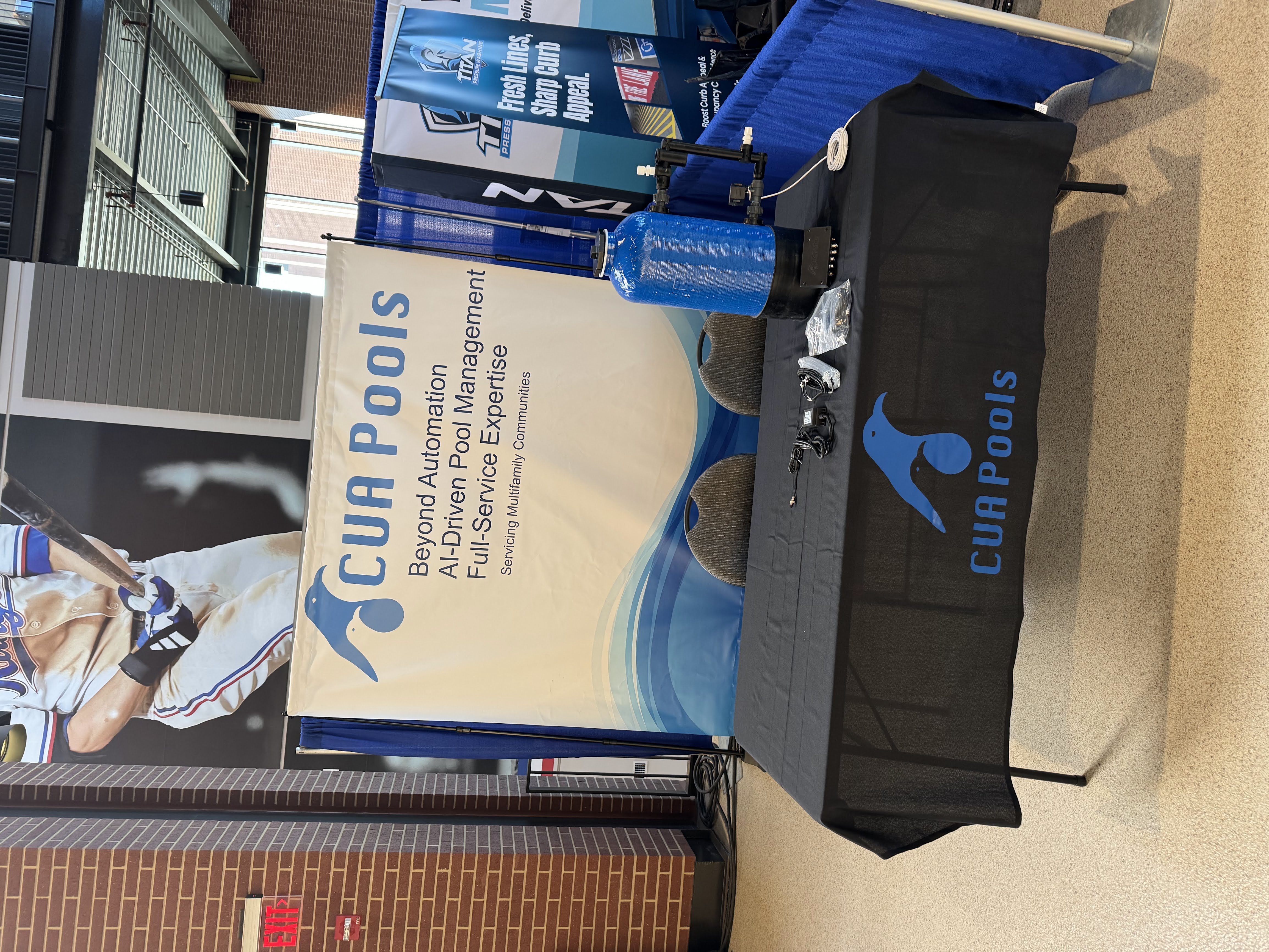
Figure A-5
Additional field view documenting installed system arrangement and connection layout.
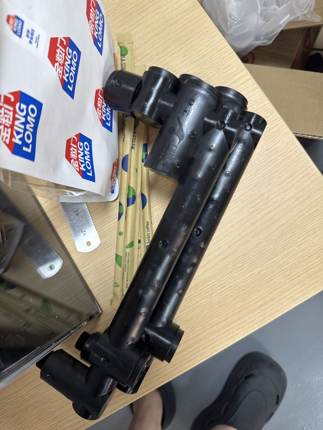
Figure A-6
Supplemental photograph showing system component construction and installed hardware details.
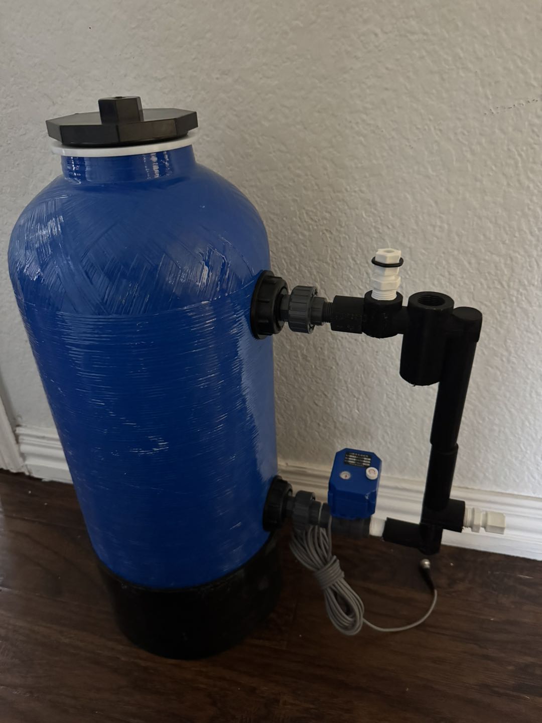
Figure A-7
Additional installation photograph from the CUASCHEM5 compliance submission set.

Figure A-8
Additional system view from the CUASCHEM5 compliance submission set.